Hello friends, today we are oing to see the fiber optics cable or optical fiber.
Introduction
An optical transmission system has three components: the light source, the transmission medium, and the detector. The transmission medium is an ultra-thin fiber of glass. The detector generates an electrical pulse when light falls on it.
This transmission system would leak light and to be useless in practice. When a light ray passes from one medium to another, e.g. from fused silica to air, the ray is refracted at the silica/air boundary. Rays also reflected internally, and bouncing around at different angles. Each ray is to have a different mode so a fiber having this property is called a multi-mode fiber.
If the fiber’s diameter is reduced to a few wave length of light, the fiber acts like a wave guide, and the light can only transmit in a straight line, without bouncing called single-mode fiber.
Single mode fibers are more expensive but can be used for longer distances.
 |
| Internal Reflection of fiber optics |
Fig. (a) Three examples of a light ray from inside a silica fiber impinging on the air/silica boundary at different angles, (b) Light trapped by total internal reflection.
Fiber Cables
Fiber optic cables are similar to coax, except without the braid. Fig is as follows. At the center of these fiber optic cables is the glass core through which light transmit. The core is surrounded by a glass cladding with a lower index of refraction than the core, to keep all the light in the core. Next a thin plastic jacket to protect the cladding. Fibers are typically grouped in bundles, protected by an outer sheath.
In multi-mode fibers, the core is 50 microns in diameter and in single mode fibers the core is 8 to 10 microns.
Fiber sheaths are normally laid in the ground within the meter of the surface. And in deep water they just lie on the bottom.
 |
| Fiber Cable |
fig. (a) side view of a single fiber, (b) End view of a sheath with three fibers.
Fibers can be connected in three different ways.
- Plugged into fiber sockets.
- They can be spliced mechanically.
- Two pieces of fiber can be fused (melted) to form a solid connection.
LEDs (Light Emitting Diodes) and semiconductor lasers are used for light sources to do the signaling. The receiving end of an optical fiber consists of a photodiode, which gives off an electrical pulse when struck by light. The typical response time of a photo diode is 1 nsec, which limits data rates to about 1 Gbps. The error rate is small but thermal noise is an issue.
Fiber Optic Networks:
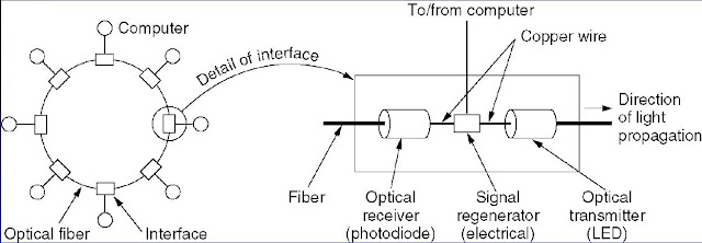
Fiber optics can be used in LANs as well as in long-haul transmission. An interface is used at each computer to passes the light pulse stream through to the next link and serves as a T junction to allow the computer to send and accept messages.
 |
| Fiber Optic Ring |
fig. A fiber optic ring with active repeaters.
There are two types of interfaces used in fiber optics network.
Passive Interface
It consists of two taps fused onto the main fiber. One for Led or laser diode at the end of it for transmitting signal and the other has a photo diode for receiving at the other end. The tap is completely passive and extremely reliable, a broken LED or photo diode does not break the ring. It just takes one computer off-line.
Active Repeater
The incoming light is converted to an electrical signal, regenerated to full strength if it has been weakened, and re transmitted as light by using ordinary copper wire as a interface. If an active repeater fails, the ring is broken and the network goes down.
How you found this article, is
this useful? I'm sure this will help you more. If you want more
information please let me know through comments in the right below. Subscribed to the My Computer Tutors for updates. I will keep updating to you with latest tutorials.

Comments
Post a Comment
Your comment will inspire me, Please leave your comment